Rtd Pt100 Circuit Diagram. Below is the circuit of pt100 rtd wiring diagram: The pt100 is a commonly employed.
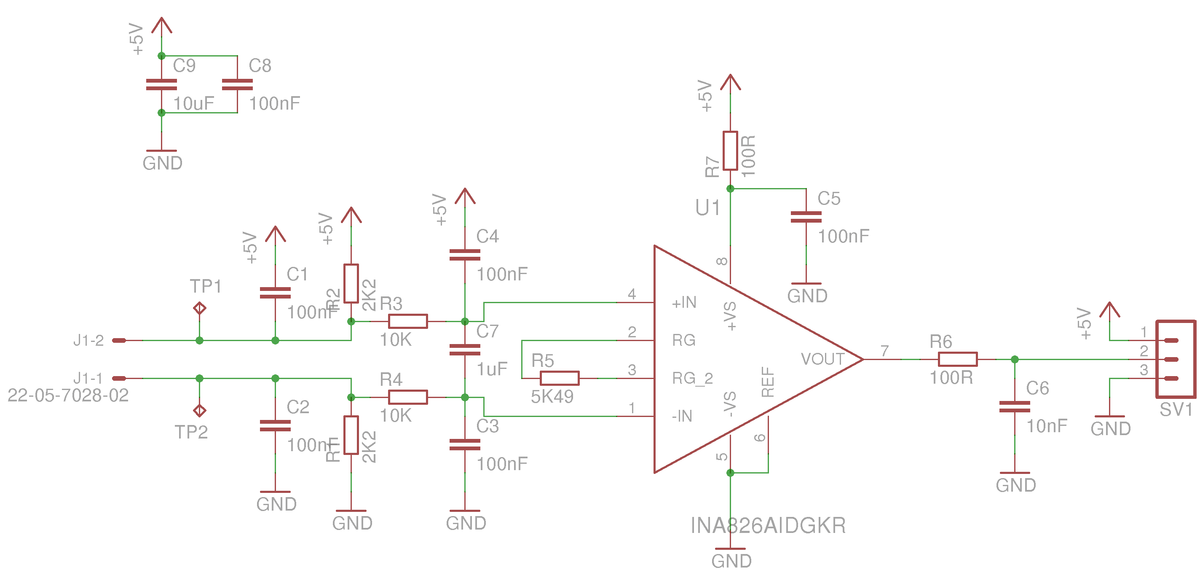
gain Working of INA826 instrumentation amplifier for Pt100 RTD from electronics.stackexchange.com
Web the pt100 3 wire temperature sensor circuit diagram is an excellent choice for accurate temperature sensing since it has extremely high accuracy and a long service. Web rtd pt100 4 wire wiring diagram by clint byrd | june 19, 2018 0 comment Below is the circuit of pt100 rtd wiring diagram:
The 100, 500 And 1000 Represent The Resistances Of Each At 0°C.
Web rtd wiring diagrams resistance measurement 2 3 or 4 wire connection how does it work and which to use temperature sensor corrosion detection lead. For iec 60751 standard pt100 rtds, the coefficients are: Determine values for the idac excitation currents and reference resistor.
Web Three Common Rtds Are The Pt100, Pt500 And The Pt1000.
Tp9237 evaluation unit for pt100 pt1000 temperature sensors ifm. Web rtd pt100 3 wire wiring diagram. Web design of pt100 temperature sensing circuit.
The Circuit Uses Only One Bridge And One Differential.
Web the temperature sensor pt100 is widely used for temperature measurement below 650 °c due to its small size, high accuracy and good stability. Web working principle of pt100 rtd sensor. Pt100 are also relatively immune to electrical noise and therefore well suited for temperature measurement in.
Web Resistance Of The Rtd At 0°C.
Web design of signal conditioning circuit for various temperature sensors. Web features platinum resistant thermometer (prt) temperature range: Web the mathematical formula for voltage divider network while choosing a fixed resistor (r) we have to consider a few things:
For A Pt100 Rtd, R.
The simpler the circuit, the better the stability. Where to use the pt100 sensor? Web rtd pt100 4 wire wiring diagram by clint byrd | june 19, 2018 0 comment